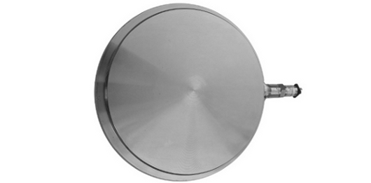
The hydraulic TOR-IDRA/CE load cell has been designed to be placed at the base of structures of armor to measure the load they transmit to their foot . Such control is essential to ensure the safety of permanent support works.
Hydraulic load cells are typically installed at the piers of galleries, below the support of the ribs, and have a shape and size such as to simplify the installation. It is also possible to provide on demand load cells for specific applications or with different specifications from the standard ones.
The cell consists of two steel plates of circular shape, machined and welded together in such a way as to create an interspace filled by a special oil and connected to an electric transducer which transforms every variation of pressure acting on the lung in a variation of signal electric with standard output 4 to 20 mA.
All sensor parts, including cables, are isolated and protected, to avoid concrete entrance within the cell; circuits and sensors are potted and protected in order to preserve the functionality of the instrument in the shock or immersion events. Reading the electrical pressure transducer data may be made through the use of a portable control unit or via an automatic data acquisition system designed for the continuous monitoring.
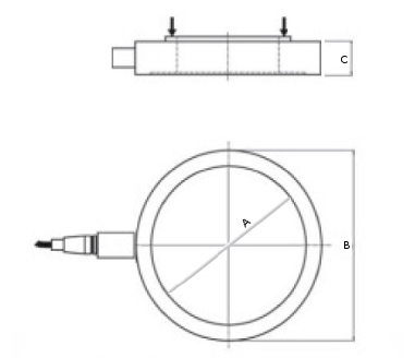
| Model | FS (t) | A (mm) | B (mm) | C (mm) |
| 1 | 190 | 200 | 220 | 38 |
| 2 | 300 | 246 | 270 | 38 |
![]() Click to enlarge image
Click to enlarge image


| Material | Stainless steel with corrosion protection |
| Nominal load | 190, 300t |
| Supply voltage | 8 - 32 V dc |
| Output | 4 - 20 mA (2 cables) |
| Linearity | 0,25 % of full scale |
| Operating temperature | -40 / +100°C (-40 / +212°F) |
| Protection class | IP 67 |
| Sensor type | Piezoresistive |
| Sensor body | Stainless stees AISI 303 |
General precautions to be followed in the installation and assembly of load cells: